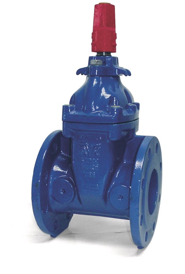
AVK GATE VALVE, RESILIENT SEATED, PN25
CC, Stem Cap, AS 2129 F, DN50-DN300
Contact
AVK Australia Civil
559A Grand Junction Road Wingfield SA 5013 Sales and Technical enquiry
Resilient seat gate valve for water, sewage and other neutral liquid applications to max. 70°C. For AS/NZS 4020 compliance, max. 40°C.
AVK gate valves are designed with built-in safety in every detail. The wedge is fully vulcanized with AVK’s own drinking water approved EPDM rubber compound. It features an outstanding durability due to the ability of the rubber to regain its original shape, the double bonding vulcanization process and the sturdy wedge design. The triple safety stem sealing system, the high strength stem and the thorough corrosion protection safeguard the unmatched reliability.
| Variant 57/80-001 | |
|---|---|
| Connection: | Flanged |
| Material: | Ductile Iron |
| DN: | DN50 - DN300 |
| PN: | PN25 |
| Closing direction: | Clockwise Close |
Features
- For water, sewage and neutral liquid applications
- Valve designed for use up to 70°C
- Where applicable; for AS/NZS 4020 compliance, max temp = 40°C
- Wedge nut designed as a fixed, integral part of the wedge which prevents vibration and ensures durability
- Wedge core fully vulcanized with drinking water approved EPDM rubber in a sophisticated process that eliminates creeping corrosion underneath the rubber
- Wedge shoes in PA and guide rails on the body make the wedge slide easily up and down regardless of differential pressure
- A large conical stem hole going all the way through the wedge ensures circulation and prevents stagnant water
- Stainless steel stem with wedge stop and rolled threads for high strength
- Full circle thrust collar keeps the stem firmly lined up and ensures low operating torque
- Triple safety stem seal with an NBR wiper ring outermost to protect against contamination from outside, in the middle four NBR O-rings around the radial bearing and innermost an EPDM lip seal as main seal to the system pressure
- Bonnet gasket in EPDM with a circular cross-section, fixed in a recess to avoid blow-out
- Counterbored stainless steel bonnet bolts, sealed with hot-melt and encircled by the bonnet gasket
Downloads
| AVK_Gate valves_animation_2022.mp4 |
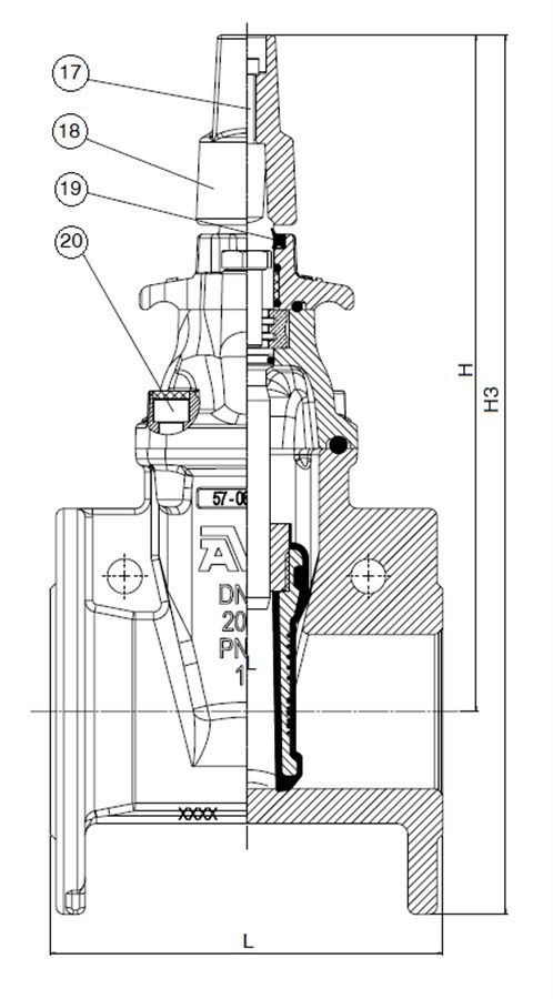
Reference nos. and dimensions:
| AVK ref. no. | DN mm |
Flange drilling |
L mm |
H mm |
H3 mm |
W mm |
D mm |
Dh mm |
Theoretical weight/kg |
|---|---|---|---|---|---|---|---|---|---|
| 57-050-80-2748120 | 50 | AS2129 F | 178 | 320 | 402 | 165 | 127 | 18 | 17 |
| 57-080-80-2748120 | 80 | AS2129 F | 203 | 350 | 350 | 200 | 165 | 18 | 19 |
| 57-100-80-2748120 | 100 | AS2129 F | 229 | 380 | 497 | 235 | 191 | 18 | 28 |
| 57-150-80-2748120 | 150 | AS2129 F | 267 | 485 | 635 | 300 | 260 | 22 | 51 |
| 57-200-80-2748120 | 200 | AS2129 F | 292 | 596 | 776 | 360 | 324 | 22 | 73 |
| 57-250-80-2748120 | 250 | AS2129 F | 330 | 680 | 892 | 425 | 381 | 25 | 107 |
| 57-300-80-2748120 | 300 | AS2129 F | 356 | 755 | 998 | 485 | 438 | 25 | 144 |
Components
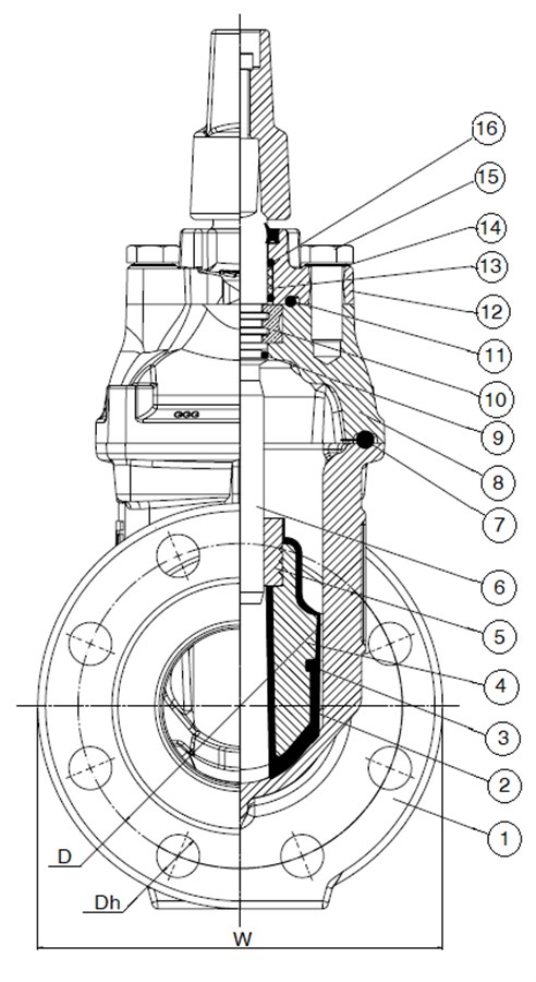
| 1. | Body | Ductile iron GJS-500-7 (GGG-50) |
| 2. | Wedge rubber | EPDM rubber |
| 3. | Wedge shoe | Polyamide |
| 4. | Wedge core | Ductile iron |
| 5. | Wedge nut | Brass, DZR CW602N |
| 6. | Stem | Stainless steel 1.4057 |
| 7. | Bonnet gasket | NBR rubber |
| 8. | Bonnet | Ductile iron GJS-500-7 (GGG-50) |
| 9. | O-ring | NBR rubber |
| 10. | Thrust collar | Brass, DZR CW602N |
| 11. | O-ring | NBR rubber |
| 12. | Gland flange | Ductile iron GJS-500-7 (GGG-50) |
| 13. | Bushing | Polyamide |
| 14. | Washer | Stainless steel A4 |
| 15. | Bolt | Stainless steel A4 |
| 16. | O-ring | NBR rubber |
| 17. | Bolt | Stainless steel A2 |
| 18. | Stem Cap | Ductile iron GJS-500-7 (GGG-50) |
| 19. | Wiper ring | NBR rubber |
| 20. | Bolt | Steel, galvanized 12.9 |
Standards
- Face-to-face dimension according to AS2638.2
- Flange drilling: AS 2129 F